 steellab
We supply Gate Valve, select your favorite Valve to send us an inquiry email or leave us a message, we will contact you within 24 hours, for your quotation.
PZ673H
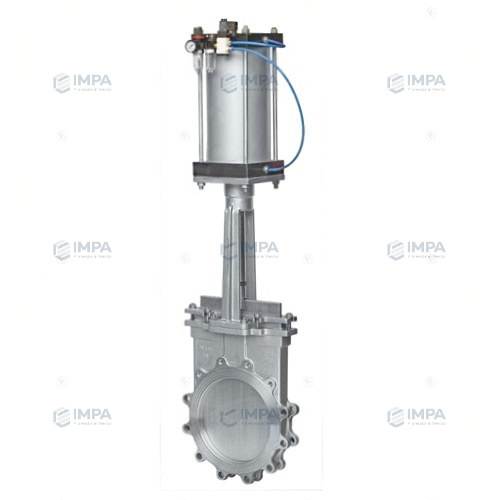
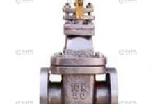
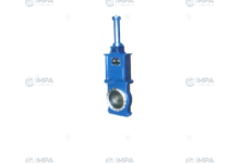
A knife gate valve, also known as a knife-type gate valve, knife gate valve, slurry valve, or mud valve, uses a gate as its opening and closing element. The gate’s movement direction is perpendicular to the fluid direction. It cuts off the medium by using a knife-shaped gate capable of cutting fibrous materials. The gate has two sealing surfaces. In the most common type of gate valve, the two sealing surfaces form a wedge shape, with the wedge angle varying depending on the valve parameters, typically 50 degrees. The gate of a wedge-type knife gate valve can be made as a single piece, called a rigid gate; or it can be made as a gate that can produce slight deformation to improve its manufacturability and compensate for deviations in the sealing surface angle during processing; this type of gate is called a flexible gate. The valve body does not actually have a chamber. The gate rises and falls within a side guide groove and is pressed tightly against the valve seat by a lug at the bottom. For higher media sealing performance, an O-ring seal valve seat can be used to achieve bidirectional sealing. Knife gate valves have a smaller installation space, lower operating pressure, are less prone to debris accumulation, and are relatively inexpensive.
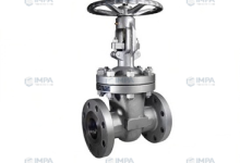
When a knife gate valve is closed, the sealing surface can be sealed solely by the pressure of the medium. This means the medium pressure forces the sealing surface of the gate plate against the valve seat on the other side to ensure a seal; this is called self-sealing. Most gate valves use forced sealing, meaning that when the valve is closed, external force is required to press the gate plate against the valve seat to ensure a tight seal. These valves should generally be installed vertically in pipelines.
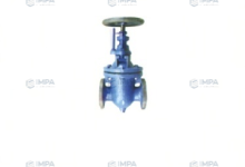
Knife gate valve actuation methods: manual, sprocket, electric, pneumatic, hydraulic, bevel gear, electro-hydraulic, and pneumatic-hydraulic actuation, etc. Knife gate valve shape: rising stem and non-rising stem. Knife gate valve materials: cast iron, cast steel, carbon steel, stainless steel, fluoropolymer-lined, etc. Knife gate valve sealing: hard seal, soft seal, single-sided seal, double-sided seal, and various other sealing materials.
Ultra-thin knife gate valves, with their advantages of small size, low flow resistance, light weight, easy installation, and easy disassembly, have completely solved the problems of high flow resistance, heavy weight, difficult installation, and large footprint associated with ordinary gate valves, flat gate valves, ball valves, globe valves, regulating valves, and butterfly valves. Since their advent, knife gate valves have replaced a large number of general-purpose shut-off and regulating valves. Today, the United States and Japan are the largest users of knife gate valves globally.
The application range of knife gate valves includes:
- Mining, coal washing, and steel industries – used for coal washing pipelines, filter slurry pipelines, and ash discharge pipelines;
- Purification devices – used for wastewater, slurry, sewage, and clarified water containing suspended solids;
- Paper industry – used for pulp and feed-water mixtures of any concentration;
- Power plant ash removal – used for ash slurry.
- For diameters of 150mm and above, a fully enclosed structure is adopted, which can more effectively open and prevent leakage.
Thirteen, fluororubber sealing surfaces achieve a sealing effect and improve operating temperature.
Fourteen, the rubber sealing surface is directly vulcanized into the valve body and will not fall off.
Installation and Usage Instructions
- Before installing the knife gate valve, inspect the valve cavity and sealing surfaces for dirt or sand.
- Tighten all bolts evenly.
- Ensure the packing is properly tightened to guarantee both sealing performance and smooth gate opening.
- Before installation, verify the valve model, connection dimensions, and media flow direction to ensure consistency with valve requirements.
- Allow sufficient space for valve actuation during installation.
- Wiring of the actuation device must follow the wiring diagram.
- Knife gate valves require regular maintenance and should not be subjected to impacts or pressure to avoid affecting the seal.
Maintenance
- Handwheels, handles, and transmission mechanisms must not be used for lifting and must be protected from impacts.
- Double-gate valves should be installed vertically (i.e., valve stem in a vertical position, handwheel at the top).
- For gate valves with bypass valves, the bypass valve should be opened first before the main valve (to balance the pressure difference between the inlet and outlet and reduce the opening force).
- Gate valves with transmission mechanisms should be installed according to the product instruction manual.
- If the valve is frequently opened and closed, it should be lubricated at least once a month.
Standards:
The pressure-temperature rating of the shell material conforms to GB9131.
The structural length and limit deviations of the valve body conform to GB/T 15188.2.
Special requirements for flange connection dimensions and sealing surface type should be specified in the order.
The valve stem and valve stem nut use trapezoidal threads, and their basic dimensions and tolerances conform to GB 5796.1~5796.4.
The connection dimensions between the bracket and the drive unit conform to GB 12222.
The valve body is made of WCB material, conforming to GB12229.
The gate valve is made of austenitic stainless steel (SS304), conforming to GB 12220 and GB4237.
The valve stem is made of 1Cr13 or 2Cr13, conforming to GB 12220.
The bracket and packing gland are made of carbon steel (WCB), conforming to GB 12229.
The valve stem nut is made of copper alloy (ZCuZn38Mn2Pb2, ZCuSn5Pb5Zn5), conforming to GB 12225.
The upper seal (packing) is made of graphite asbestos rope.
The shell test and sealing test conform to GB/T 13927.
For effective sealing performance requirements, leakage in the sealing test is calculated as 1×mm/s.
The cleaning requirements for the gas gate valve conform to JB/T 7748.
The paint color conforms to JB 106.
The packaging, storage, transportation, and quality assurance of the gas gate valve shall comply with the provisions of JB/T 7928.
Shell pressure: 1.5MPa, sealing pressure: 1.1 MPa, applicable temperature: 425℃, applicable media: sewage, gas, pulp, etc.
A dual-electrically controlled three-position five-way solenoid valve is used to control the pneumatic knife gate valve cylinder. A three-position switch is used, which can control the gate valve to stop at the upper limit, lower limit, and any other position.
- When the gate valve stops at the upper or lower limit position, the limit switches at the upper and lower limits send a set of normally open or normally closed independent signal contacts. These can be used for status indication.
- When the gate valve stops at the upper or lower limit position, the limit switches at the upper and lower limits automatically cut off the power supply to the corresponding control coil of the solenoid valve. This ensures that the solenoid valve’s control coil is not energized when the gate valve stops at the upper or lower limit position for an extended period, preventing the solenoid coil from overheating, increasing the service life of the solenoid valve, and greatly improving reliability.
- When the gate valve remains in the upper or lower limit position for an extended period, the air supply is cut off, consuming no air, but the air pressure in the locking cylinder remains within the cylinder, ensuring reliable stopping.
- During cylinder switching, if the control power is cut off, the air supply to and from the cylinder is also cut off simultaneously. The air pressure in the locking cylinder remains within the cylinder. If there are no leaks in the cylinder piston, solenoid valve, or joints, the gate valve can remain in any position for an extended period.